EventTrak Configuration for Tunneling I-O or Relay Signal between Two IBIO2100's (IntelliBox units)
- Jane
I have 2 IntelliBox units and would like to recieve a digital I/O signal and send to the other unit to trigger it's relay. How would I go about this?
Below is the method to set this up.
Title: EventTrak Configuration for Tunneling a I/O or Relay Signal between Two IBIO2100Es
Summary: A digital I/O Signal received by IBIO2100#1 will make it send a trigger message to IBIO2100#2 to toggle it’s relay.
Two IntelliBox units are needed to tunnel a Digital I/O signal to trigger a Relay of the other. Unit one will be getting the 3-8Vdc digital I/O signal. Unit two will trigger its 9-30Vdc relay.
The entire EventTrak configuration setup is done from the IntelliBox web manager.
Log in to the unit via a web browser typing in its IP address in the address bar.
Example: 192.168.1.22
A summary of the process that goes on inside and between the master and slave IntelliBox units is described below.
Both ‘Master’ and ‘slave’ IntelliBox units will need to use a serial ports with a loopback connector on it to make this EventTrak work:
* Master IntelliBox#1 will send out the string ‘Trigger’ from it's serial port 2 through the loop back adapter back into itself.
* With Connect Mode configured in the master, it will take the string and send it to a designated IP address and TCP port number of the looped back serial port of the slave IntelliBox.
* The slave IntelliBox#2 will send the message out the designated serial port and through the loopback back into itself.
* An EventTrak configuration setup on the slave IntelliBox is running to monitor the match string “Trigger” then activate the relay.
* The relay will stay triggered until the voltage goes low on the other end, forcing the 1st unit to send a 2nd string “Reset” to the 2nd unit and turning off the relay.
Once a pair of IntelliBox device servers have been configured, other IntelliBoxes can be configured by importing .xml files extracted from previously configured IntelliBox units. In the web manager, click on -
* XML Link on the Left Menu
* Then Import configuration link
* Select 'Configuration from External file'
* Click ‘Browse’ and locate the XML file to import. Click ‘Import’ to load into the IntelliBox.
* Click Submit
Directions for setup without the XML
For Both Units
Line 2 needs to be set up this way on each unit ( We are using the 2nd serial port as it is only RS-485. This leaves port 1 available as a console port or for a device connection.)
* Click on Line on the left menu
* Select ‘Line 2’ link
* Click ‘Configuration’
In the Configuration Menu, use the following settings (see illustration):
Interface: RS485 Full-Duplex (RS485-4wire) – to allow loopback connection on port
State: Enabled
Protocol: Tunnel
Baud Rate: 9600
Parity: None
Data Bits: 8
Stop Bits: 1
Flow Control: None
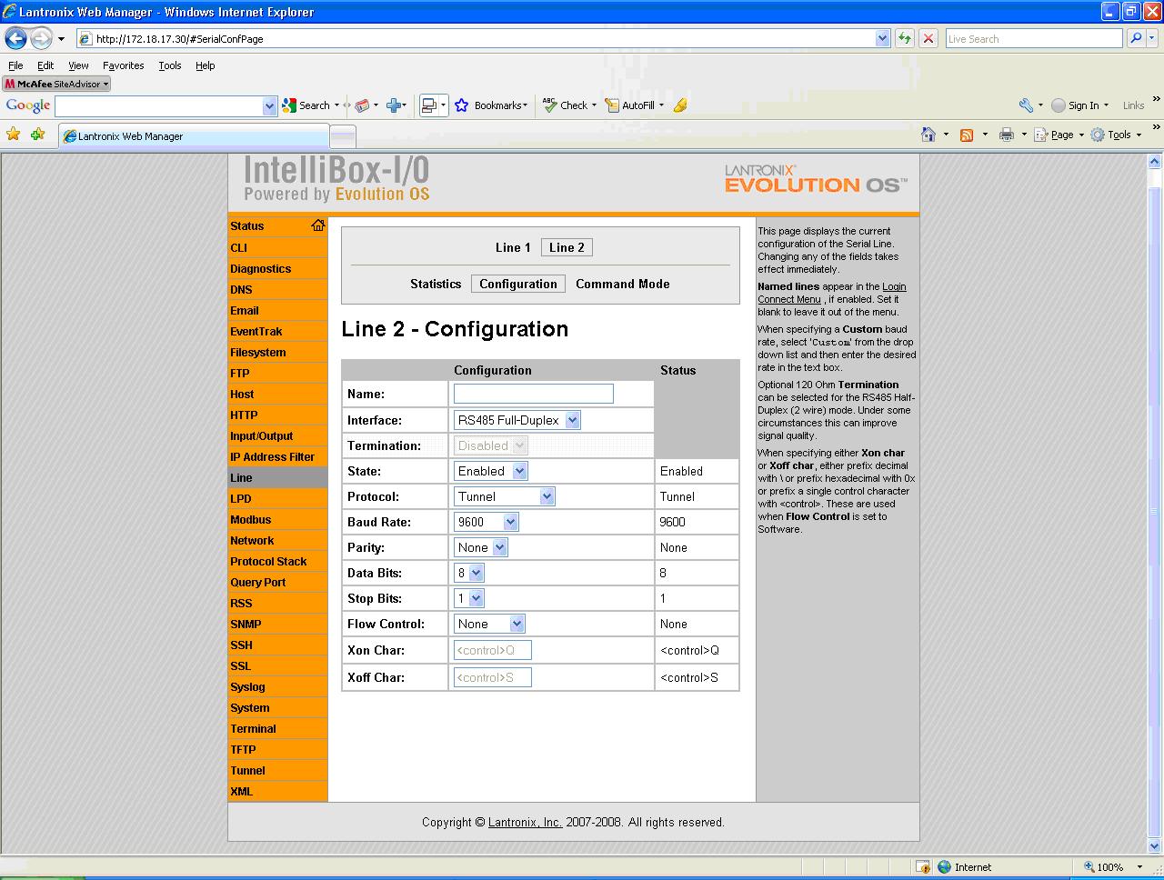
Click on the thumbnail above for a full sized screen shot
A loopback connection needs to be placed on the serial channel 2 port of the IntelliBoxes. (See screen shot below)
To do this, place a jumper wire, (a piece of stiff bare wire or metal paperclip,) connecting Tx- to Rx – and Tx+ to Rx+.
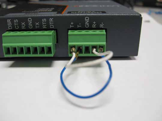
Click on the thumbnail above for a full sized screen shot
EventTrak Configuration for the Master Unit
Master Unit will be getting the digital I/O signal to send the ‘Trigger’ match string to activate the relay on the slave IntelliBox.
Tunnel Configuration
Click on Tunnel in orange menu options to the left
Click on ‘Tunnel 2’ link.
Click on ‘Accept mode’ line from the upper menu
Click the Radio button for 'Off' under Block network data Mode prevents a message ‘loop’ where the match string gets passed on back and forth between the Master and slave IntelliBoxes in a never-ending loop.
Click Submit button.
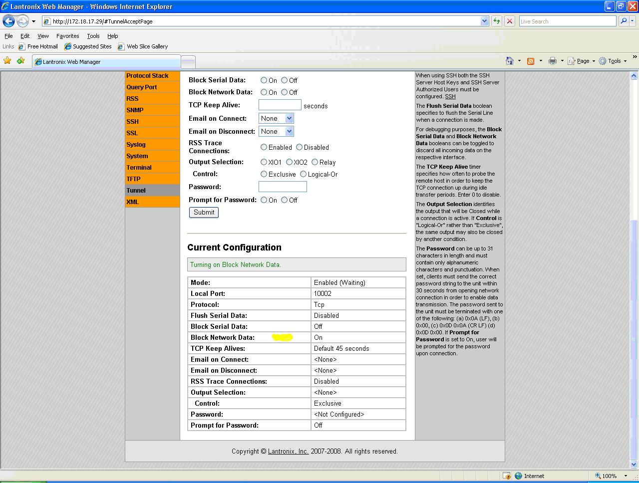
Click on the thumbnail above for a full sized screen shot
From Tunnel Menu > Tunnel 2, click on ‘Connect Mode’
Select Mode = 'Enabled'
Set the Remote address to the slave IntelliBox (eg, 192.168.1.23).
Set the Remote Port to port number of the serial line 2 of the slave unit (eg, 10002).
The rest of the settings can be left unchanged (defaults).
Click the Submit button.
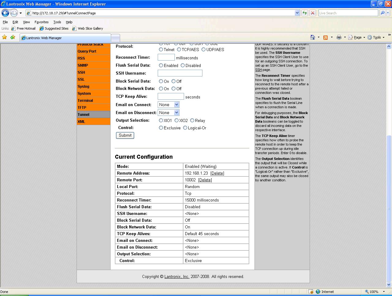
Click on the thumbnail above for a full sized screen shot
Input/Output Configuration
Click on Input/Output link on the left menu.
Set the XIO1 to ‘Input’ so it can read the incoming data
Wire up 1+ and 1- terminals of digital I/O #1 to its partner device providing the I/O input.
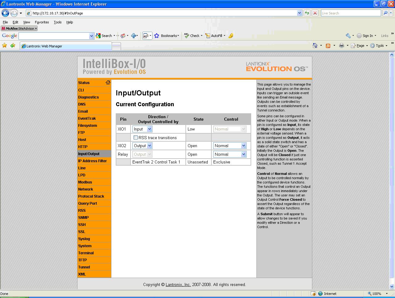
Click on the thumbnail above for a full sized screen shot
EventTrak Configuration (Master Unit)
Click on EventTrak on the left menu.
Click on ‘EventTrak 2’link.
Click on ‘Control’ link.
Click on ‘Task 1’ link.
Because the task is multi-layered (has several steps), we configure the steps as follows:
In Step “A”,
Enter Description: ‘Wait for IO One to go High’ (optional, but recommended)
For ‘Advance to step “B” if:’, select ‘XIO1 Low to High’ from drop-down selection.
For ‘Upon Advance’, select ‘Send on Line’ from the drop-down box. Another drop-down box appears. Select the action ‘Send Text’. Enter ‘Trigger’ in the next field.
Leave ‘Fallback to Step ‘A’ If:’ unchanged/default value ‘Add an Event’.
In Step “B”,
Enter Description: ‘Wait for IO One to go Low’ (optional, but recommended)
Set ‘Advance to Step ‘C’ If:’ to value ‘XIO1 High to Low’ from the drop-down box.
For ‘Upon Advance’, select ‘Send on Line’ from the drop-down box. Another drop-down box appears. Select the action ‘Send Text’. Enter ‘Reset’ in the next field.
No further Steps need to be configured.
Click Submit.
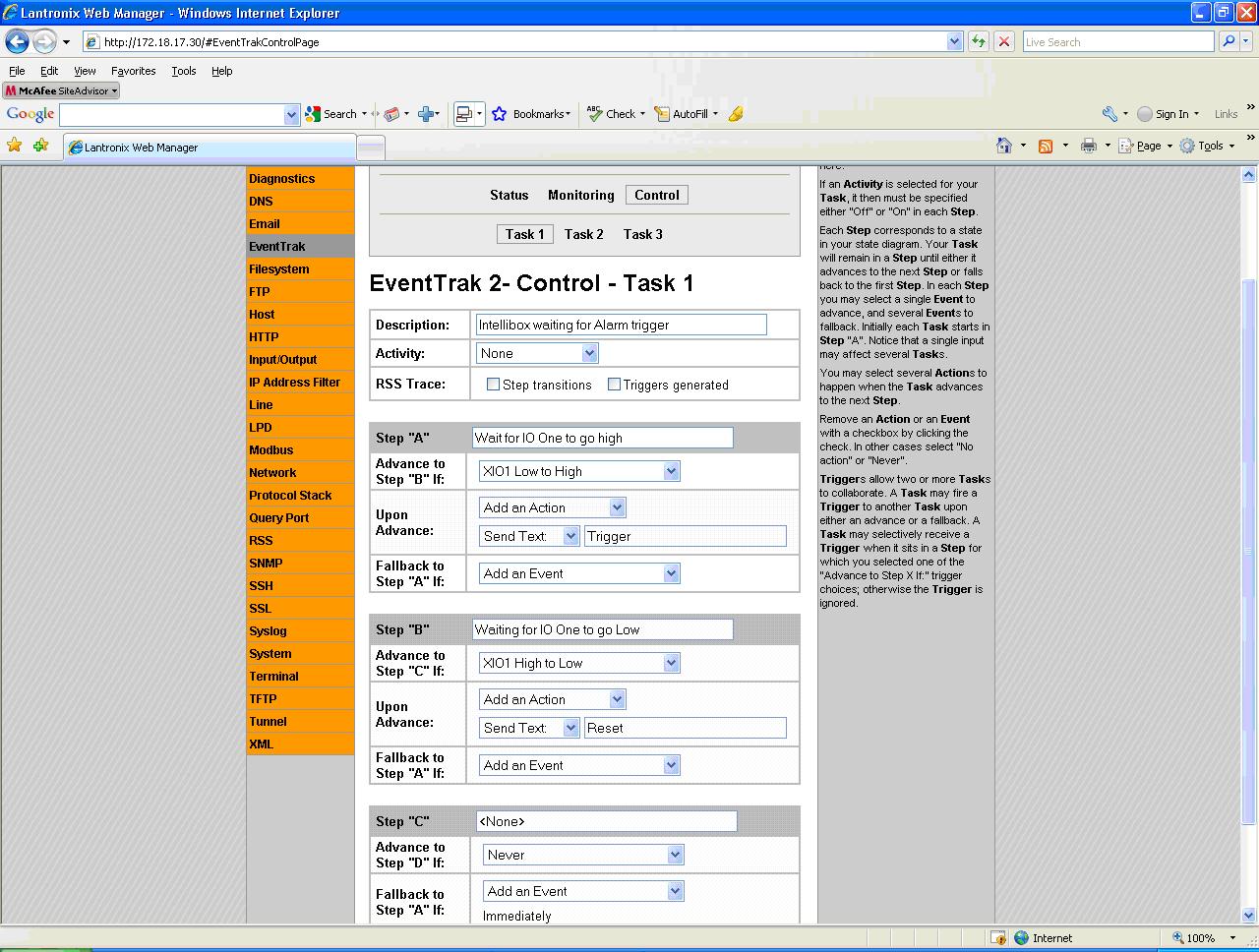
Click on the thumbnail above for a full sized screen shot
EventTrak Configuration for the Slave Unit
The Slave unit will have the EventTrak configured to trigger the Relay
EventTrak Control Configuration (Slave Unit)
Click on ‘EventTrak’ on the left menu.
Click on ‘EventTrak 2’ link.
Select ‘Control’, then ‘Task 1’
Set ‘Activity’ to ‘Relay’ from drop-down box.
Set ‘Output Control’ to ‘Exclusive’ (default setting).
In Step “A”,
Enter Description: ‘Waiting for signal from box 1’ (optional, but recommended)
Select Relay = OFF (NO = Open, NC = Closed)
For ‘Advance to step “B” if:’, select ‘Matched String 1’ from the drop-down box.
In Step “B”,
Enter Description: ‘Activating the Relay’ (optional, but recommended)
Select Relay: ON (NO = Closed, NC = Open)
For ‘Advance to step “C” if:’, select ‘Matched String 2’ from the drop-down box.
In Step “C”,
Enter Description: ‘Triggered to turn off’ (optional, but recommended)
Relay: OFF (NO = Open, NC = Closed)
Set ‘Advance to step “D” if:’ to ‘Never’.
Click Submit.
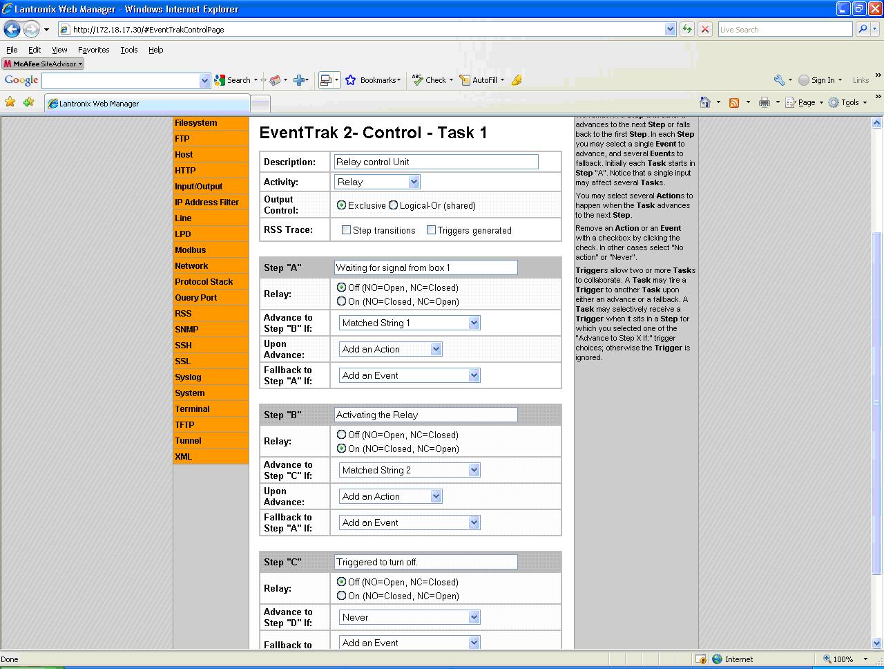
Click on the thumbnail above for a full sized screen shot
EventTrak Monitoring Match 1
Click on EventTrak on the left menu.
Click on ‘EventTrak 2’ link.
Select ‘Monitoring’, then ‘Match 1’.
For ‘Match string’ field, enter the word “Trigger”.
Mode = ‘Text’, Case Sensitive = ‘No’.
Click Submit.
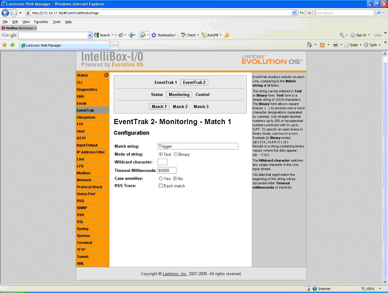
Click on the thumbnail above for a full sized screen shot
EventTrak Monitoring Match 2
Click on EventTrak on the left menu.
Click on ‘EventTrak 2’ link.
Select ‘Monitoring’, then ‘Match 2’.
For ‘Match string’ field, enter the word “Reset”.
Mode = ‘Text’, Case Sensitive = ‘No’.
Click Submit.
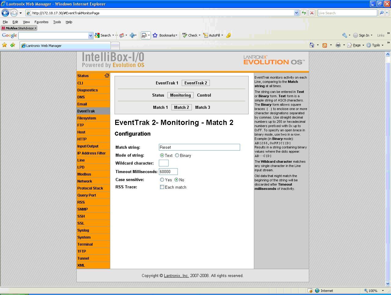
Click on the thumbnail above for a full sized screen shot
[Originally Published On: 07/23/2009 08:11 AM]