Modbus Serial Tunnel
- Jane
How can I setup a serial tunnel between two Lantronix device servers using the Modbus protocol?
Modbus Serial Tunnel
In the scenario below, one Lantronix device server will be setup with a Modbus master attached to its serial port. All other Lantronix device servers will have Modbus slaves attached to their serial port. In most cases there are several aspects involved in this type of configuration. These aspects normally include:
1. A PC running software used to manage the PLC or Modbus devices. 2. A Lantronix device server with Modbus support attached to a Modbus master. In this case the master is the PC above. 3. A Lantronix device server with Modbus support attached to a Modbus slave device(s) such as PLC's. 4. A Modbus device such as a PLC attached to a a Lantronix device server with Modbus support.
The diagram below illustrates this topology.
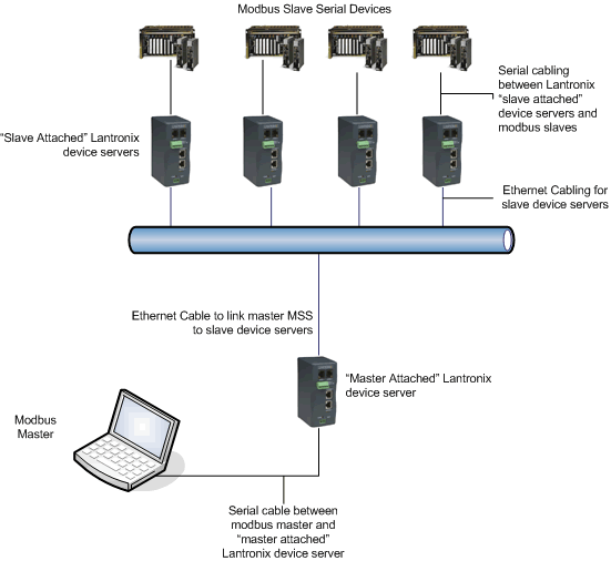
In this scenario the "Master Attached" Lantronix device server will have a Modbus master connected to its serial port. The PC running the 3rd party software and the "Master Attached" Lantronix device server will be directly connected via a serial cable. The "Master Attached" Lantronix device server will then be configured to send Modbus messages over the Ethernet to the "Slave Attached" Lantronix device server(s). Each "Slave Attached" Lantronix device server will have Modbus slaves connected to their serial ports. This will allow each "Slave Attached" Lantronix device server to receive Modbus messages from the 3rd party software running on the PC.
The settings in the Lantronix devices should be configured as shown below. Note, the IP configuration in each device is an example. The IP settings in your device will be different and based on the network on which you install your devices.
Master Attached Lantronix Device Server:
Serial Number nnnnnnn MAC address hh:hh:hh:hh:hh:hh Software Version Vnn.n (nnnnnn)
Press Enter to go into Setup Mode, wait to close
Lantronix, Inc.
1) Network/IP Settings:
IP Address ................. 192.168.001.004
Default Gateway ............ 192.168.001.001
Netmask .................... 255.255.255.000
2) Serial & Mode Settings:
Protocol ................... Modbus/RTU,Master attached
Serial Interface ........... 19200,8,N,1,RS232
3) Modem Control Settings:
RTS Output ................. Fixed High/Active
4) Advanced Modbus Protocol settings:
Character,Message Timeout .. 00500 ms,05000 ms
5) Unit ID -> IP Address Table:
000-254: 192.168.001.006
Configuration Options Explanation:
- Network/IP Settings - These settings are determined by the network you are configuring the Lantronix Device Server to run on. These will vary from network to network. You should contact your network administrator for this information.
- Serial & Mode Settings - These settings determine what the Lantronix Device Server will be used for. Detailed information on these settings can be found in your products documentation at the link below:
Lantronix Product Documentation
- Modem Control Settings - This feature allows you to hold the RTS pin on the serial port high or low.
- Advanced Modbus Protocol Settings - 5. Unit ID -> IP Address Table - This table is where you designate which Modbus nodes are attached to which TCP/IP node.
- Unit ID -> IP Address Table - This table tells the Master Attached Lantronix device which IP address on the network has which Modbus slave addresses attached to it. A range of slave addresses can be used. It is important that the proper slave address is used for each IP address.
Slave Attached Lantronix Device Server:
Serial Number nnnnnnn MAC address hh:hh:hh:hh:hh:hh Software Version Vnn.n (nnnnnn)
Press Enter to go into Setup Mode, wait to close
Lantronix, Inc.
1) Network/IP Settings:
IP Address ................. 192.168.001.006
Default Gateway ............ 192.168.001.001
Netmask .................... 255.255.255.000
2) Serial & Mode Settings:
Protocol ................... Modbus/RTU,Slave(s) attached
Serial Interface ........... 19200,8,N,1,RS232
3) Modem Control Settings:
RTS Output ................. Fixed High/Active
4) Advanced Modbus Protocol settings:
Slave Addr/Unit Id Source .. Modbus/TCP header
Modbus Serial Broadcasts ... Enabled (ID 0) Character,Message Timeout .. 00500 ms,05000 ms
Configuration Options Explanation:
- These settings are determined by the network you are configuring the Lantronix Device Server to run on. These will vary from network to network. You should contact your network administrator for this information.
- These settings basically determine what the Lantronix Device Server will be used for. Detailed information on these settings can be found in our online manuals at the link below:
Lantronix Product Documentation
- This feature allows you to hold the RTS pin on the serial port high or low.
- Advanced Modbus Protocol Settings - This setting will allow you to designate whether or not the Lantronix Device Server will look in the Modbus TCP header for the unit ID the message is destined for. You can also enable or disable Modbus broadcasts using this setting. Lastly, character and message timeout tells the Lantronix Device Server how long it should wait before it times out if it has not received.
[Originally Published On: 04/26/2006 12:57 PM]