What are the pinouts and board diagrams and dimentions of a Micro?
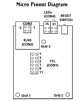
Micro Connector Locations
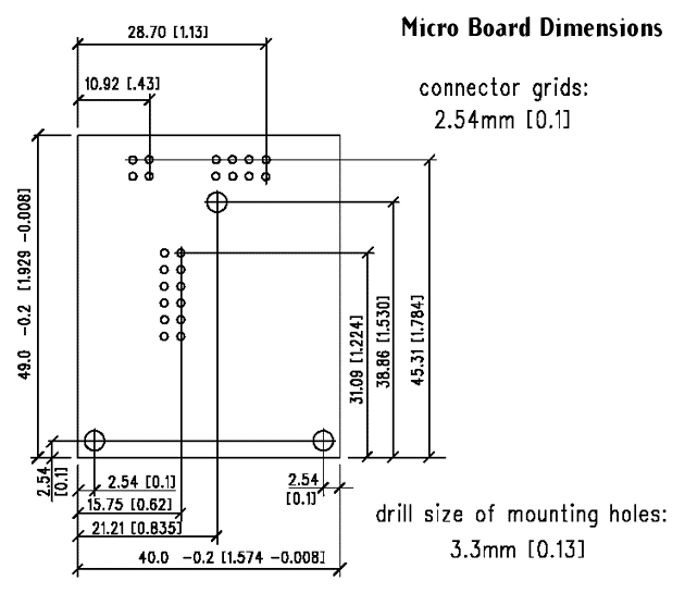
Micro board dimensions
CON1 (2 x 6 Pins)
CON2 (RJ45)
Pin
Function
Pin
Function
1
2
3
4
5
6
7
8
9
10
11
12
+5V
GND
RXA (Input)
TXA (Output)
RTSA (Output)
DTRA (Output)
CTSA (Input)
DCDA (Input)
Reserved
RESET, pulled low
RXB (Input - optional)
TXB (Output - optional)
1
2
3
4
5
6
7
8
TX+
TX-
Rx+
NC
NC
RX-
NC
NC
CON3
(2 x 2 Pins in place of RJ45)
CON4
(2 x 4 Pins in place of LEDs)
Pin
Function
Pin
Function
1
2
3
4
TX+
TX-
RX+
RX-
1
2
3
4
5
6
7
8
+5V
+5V
LED2
LED1
+5V
+5V
LED3
LED "good link"
[Originally Published On: 10/21/2013 11:11 AM]