RJ45 Serial Pinouts and cables for Lantronix console and device servers
How do I wire cables for terminals and modems for current Lantronix products with RJ45 serial ports?
Below are the serial pinouts for RJ45 serial ports on all current Lantronix Console Servers and Multi-Port Device Servers with 8 or more ports.

Note: The SLC8000 line of secure console servers has switchable RJ45 pinouts. As shipped the device ports use a Reverse Pinout:
    RJ45

RTS 8
DTR 7
TX+ 6
SGD 5
SGD 4
RX+ 3
DSR 2
CTS 1

This allows the connection of Cisco, Sun and other equipment with RJ45 serial ports using a straight-through RJ45 cable, e.g. an Ethernet patch cable.
You can either reverse the pinout on the SLC8000 end of the diagrams below, or uncheck the "Reverse Pinout" checkbox on the Devices->Device Ports configuration page for the port you will be connecting to: 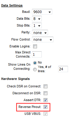
From the command line use the command:
> set deviceport port n reversepinout disable
where 'n' is the number of the deviceport you want to modify.
~~~~~
Two diagrams are presented for each application below, one for an RJ45-RJ45 straight-through cable to an RJ45/DB9 or RJ45/DB25 "hood" adapter, the other for a cable with an RJ45 on one end and a DB9 or DB25 connector on the other end.
To connect a DB25 terminal to an RJ45 port, use the following cable and adapter:
               Cable            200.2067A Adapter

  RJ45       (Straight)         RJ45        DB25    Signal

RTS 1     1-------------1       1-------------5     CTS
DTR 2     2-------------2       2-----|-------6     DSR
                                      |-------8     DCD
TX+ 3     3-------------3       3-------------3     RXD
SGD 4     4-------------4       4-----|
SGD 5     5-------------5       5-----|-------7     Signal Ground
RX+ 6     6-------------6       6-------------2     TXD
DSR 7     7-------------7       7-------------20    DTR
CTS 8     8-------------8       8-------------4     RTS

For a straight cable with RJ45 on one end and DB25 on the other:

RJ45                 DB25
RTS 1 -------------- 5  CTS
DTR 2 --------|----- 6  DSR
              |------8  DCD
TX+ 3 -------------- 3  RXD
SGD 4 --------|
SGD 5 --------|----- 7  Signal Ground
RX+ 6 -------------- 2  TXD
DSR 7 -------------- 20 DTR
CTS 8 -------------- 4  RTS
To connect a DB9 terminal to an RJ45 port, use the following cable and adapter:
              Cable            200.2070A Adapter

RJ45        (Straight)         RJ45          DB9    Signal

RTS 1     1-------------1       1-------------8     CTS
DTR 2     2-------------2       2-----|-------6     DSR
                                      |-------1     DCD
TX+ 3     3-------------3       3-------------2     RXD
SGD 4     4-------------4       4-----|
SGD 5     5-------------5       5-----|-------5     Signal Ground
RX+ 6     6-------------6       6-------------3     TXD
DSR 7     7-------------7       7-------------4     DTR
CTS 8     8-------------8       8-------------7     RTS
For a straight cable with RJ45 on one end and DB9 on the other:


RJ45                 DB9

RTS 1 -------------- 8 CTS
DTR 2 ---------|---- 6 DSR
               |-----1 DCD
TX+ 3 -------------- 2 RXD
SGD 4 ---------|
SGD 5 ---------|---- 5 Signal Ground
RX+ 6 -------------- 3 TXD
DSR 7 -------------- 4 DTR
CTS 8 -------------- 7 RTS
RJ45 modem pinout:

To connect a DB25 modem to an RJ45 port, use the following cable and adapter:
               Cable            200.2073 Adapter

  RJ45       (Straight)         RJ45        DB25    Signal

RTS 1     1-------------1       1-------------4     RTS
DTR 2     2-------------2       2-------------20    DTR
TX+ 3     3-------------3       3-------------2     TXD
SGD 4     4-------------4       4-----|
SGD 5     5-------------5       5-----|-------7     Signal Ground
RX+ 6     6-------------6       6-------------3     RXD
DSR 7     7-------------7       7-------------8     DCD
CTS 8     8-------------8       8-------------5     CTS

For a straight modem cable with RJ45 on one end and DB25 on the other:

RJ45                 DB25
RTS 1 -------------- 4  RTS
DTR 2 -------------- 20 DTR
TX+ 3 -------------- 2  TXD
SGD 4 ----------|
SGD 5 ----------|--- 7  Signal Ground
RX+ 6 -------------- 3  RXD
DSR 7 -------------- 8  DCD
CTS 8 -------------- 5  CTS
To connect a DB9 DCE device to an RJ45 port, use the following cable and adapter:
               Cable            200.2071 Adapter

  RJ45       (Straight)         RJ45         DB9    Signal

RTS 1     1-------------1       1-------------7     RTS
DTR 2     2-------------2       2-------------4     DTR
TX+ 3     3-------------3       3-------------3     TXD
SGD 4     4-------------4       4-----|
SGD 5     5-------------5       5-----|-------5     Signal Ground
RX+ 6     6-------------6       6-------------2     RXD
DSR 7     7-------------7       7-------------6     DSR
CTS 8     8-------------8       8-------------8     CTS

For a straight modem cable with RJ45 on one end and DB9 on the other:

RJ45                 DB9
RTS 1 -------------- 7 RTS
DTR 2 -------------- 4 DTR
TX+ 3 -------------- 3 TXD
SGD 4 ----------|
SGD 5 ----------|--- 5 Signal Ground
RX+ 6 -------------- 2 RXD
DSR 7 -------------- 1 DCD
CTS 8 -------------- 8 CTS

On Lantronix products other than the SLC8000 when looking at the RJ45 socket with the notch for the locking

tab facing down the pins are numbered 1-8 left to right:
                         12345678

                        [||||||||]
                        [        ]
                        [__    __]
                           |__|

By default the SLC8000 pinout is reversed, 8-1 left to right so that Cisco and Sun equipment may be connected with a common straight-through RJ45 patch cable, e.g. an Ethernet cable.:
                         87654321
                        [||||||||]
                        [        ]
                        [__    __]
                           |__|

On SLC8000s this pinout can be switched back and forth between reversed and non-reversed. See the note at the beginning of this article.
[Originally Published On: 08/30/1999 05:24 PM]