DB25 RS485 2 Wire & 4 Wire Pinouts & Menu Configuration for single-port UDS and SDS device servers
What is the confguration & cable pinout for RS485 2 Wire & 4 Wire on single-port UDSs and SDSs?
To configure a single-port UDS or SDS for RS485, first telnet to the IP address of the UDS to enter the confgiuration menu. See the procedures below:
Configuration & cabling for the UDS RS485 2 Wire.
At a DOS command prompt type:
C:\telnet [ip address] 9999
Hit enter, then hit enter again within 3 seconds when you see the "Press Enter for Setup Mode" prompt. You will be prompted with menu selections simalr to the ones below:.
Change Setup:
0 Server
1 Channel 1
5 Expert
6 Security
7 Factory defaults
8 Exit without save
9 Save and exit Your choice ?
- Select 1 for the channel 1 configuration, then press Enter.
- Baudrate <9600> ? [type in your baud rate], then press Enter.
- I/F Mode <4C> ? 4F (this represents RS-485 2-Wire,8 databits, no parity and 1 stopbit), then press Enter.
- Flow <00> ? 00 (no flow control), then press Enter.
- Port No <10001> ? [type the port number of your choice, over 1024 but not 9999 or 30718], then press Enter.
- ConnectMode <C0> ? C0, then press Enter.
- Auto increment source port <N> ? N, then press Enter.
- Remote IP Address : <000> . Enter <000> . Enter <000> . Enter <000>, Enter..
- Remote Port <0> ? 0, then press Enter.
- DisConnMode <00> ? 0, then press Enter.
- FlushMode <00> ? 0, then press Enter.
- DisConnTime <00:00> ? 0 : 0, then press Enter.
- SendChar 1 <00> ? 0, then press Enter.
- SendChar 2 <00> ? 0, then press Enter.
The menu will re-display:
Change Setup:
0 Server
1 Channel 1
5 Expert
6 Security
7 Factory defaults
8 Exit without save
9 Save and exit Your choice ?
- Type 9 for save and exit, then enter.
Note: The RS485 terminals on Lantronix products are labeled TX+/RX+, TX-/RX-, while other RS485 device label their terminals "+" and "-", or B and A for two-wire connections. According to the standard EIA RS485 the A stands for the inverting signal en B for the non-inverting signal. Next to the A and B line you also need signal ground (C). Manufactures do not always follow the naming convention of the standard, however that is not a problem if the polarity of the signal lines remain constant throughout the system.
Pinouts for the UDS1100 RS485 2 Wire are as follows:
2-wire pinout diagram for the UDS-1100
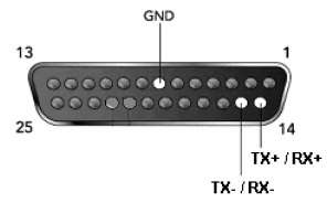
- Pins 14 & 21 and pins 15 & 22 are internally jumpered when a UDS1100 is configured for 2-wire RS485.
- Pin 14 becomes the positive signal and is connected to the positive (B) pin on your serial device.
- Pin 15 becomes the negative signal and is connected to the negative pin (A) on your serial device.
Configuration & cabling for RS485 4 Wire.
At a DOS command prompt type:
C:\telnet [ip address] 9999
Hit enter, then hit enter again within 3 seconds when you see the information about the UDS. You will be
prompted with the menu selections.
Change Setup:
0 Server
1 Channel 1
5 Expert
6 Security
7 Factory defaults
8 Exit without save
9 Save and exit Your choice ?
Select 1 for the channel 1 configuration, then enter. Baudrate <9600> ? [type in your baud rate], then enter.
- I/F Mode <4C> ? 4D (this represents RS422/RS-485 4-Wire,8 databits, no parity and 1 stopbit), then press Enter.
- Flow <00> ? 00 (no flow control, then press Enter.
- Port No <10001> ? [type the port number of your choice, over 1024 but not 9999 or 30718], then press Enter.
- ConnectMode <C0> ? C0, then press Enter.
- Auto increment source port <N> ? N, then press Enter.
- Remote IP Address : <000> . Enter <000> . Enter <000> . Enter <000>, Enter.
- Remote Port <0> ? 0, then press Enter.
- DisConnMode <00> ? 0, then press Enter.
- FlushMode <00> ? 0, then press Enter.
- DisConnTime <00:00> ? 0 : 0, then press Enter.
- SendChar 1 <00> ? 0, then press Enter.
- SendChar 2 <00> ? 0, then press Enter.
Change Setup:
0 Server
1 Channel 1
5 Expert
6 Security
7 Factory defaults
8 Exit without save
9 Save and exit Your choice ?
Type 9 for save and exit, then enter.
Pinouts for RS485 4 Wire are as follows:
4 wire RS485 pinout for the UDS-1100:

- Connect UDS pin 14 (TX non-inverting) to your serial device's RX non-inverting (B) terminal.
- Connect UDS pin 15 (TX inverting) to your serial device's RX inverting (A) terminal.
- Connect UDS pin 21 (RX non-inverting) to your serial device's TX non-inverting (B) terminal.
- Connect UDS pin 22 (RX inverting)) to your serial device's TX inverting (A) terminal.
[Originally Published On: 08/24/2005 10:46 AM]